
Introduction to Box Modeling Tutorial
To get started with modeling I picked a simple object: a chair. It only requires some basic tools: Create a box, move some points, extrude and bridge some polygons and you have a simple chair.
Commands used in this tutorial
 Create Cube (Create → Polygon Primitives → Cube)
 Extrude (Edit Mesh)
- The “pinhead” (circle on end of line protruding diagonally from the extrude tool) lets you switch between object coordinate system and one local to the chosen components.
 Bridge (Edit Mesh)
Getting Started: setting the interface and creating a project
Start Maya 🙂
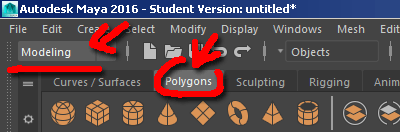
In the top right corner of the interface Switch the Menu Sets to Modeling
Click on the Polygons tab of the Shelf, the horizontal bar with icons near the top of the interface
To switch to 4 window view (three orthographic views and one perspective, click on (or hover your mouse over) the perspective view that is shown by default and hit the spacebar (do not hold, that brings up a menu)
In Maya, you always work in a project. You should create a project on your drive to work in. Anything saved on the computers in the lab (the default project is located on the C drive in the user directory) is erased when the machine reboots.
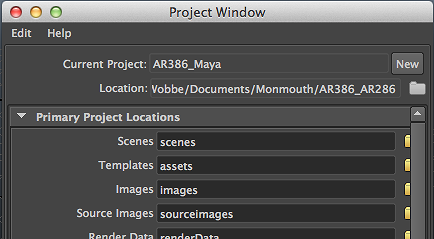
- In the top menu bar, go to File → Project Window
- In the new project window that pops up, hit the New Button
- To the right of the Location field there is a Browse icon (the folder). Click on it and navigate to the directory on your own drive where you want your project to be saved
- Give your project a clear name. A directory with this name will be created in the directory you chose
- All the other fields determine where things will get saved within the project directory.
- If left blank. everything will be saved in the same directory, making a big mess. Leave the pre-filled values as they are. This will result in a lot of subdiretories. More than you need right now, empty directories do not take up disk space so best practice is to keep all defaults.
If you already have a project, you go to File → Project → Set and choose the project directory
Create a Cube
We want to interactively create a polygon. To do this, check File > Create > [Objects] Polygon Primitives > Interactive Creation found near the bottom of that drop down menu,
On the shelf, click on the Create Cube icon
If a cube just appeared in the middle of your grid, you did not set interactive creation properly. Hit delete and try again.
Draw a small square in the middle of the grid holding down the LMB. Release the LMB and pull the square up into a relatively flat box, again holding down the LMB.
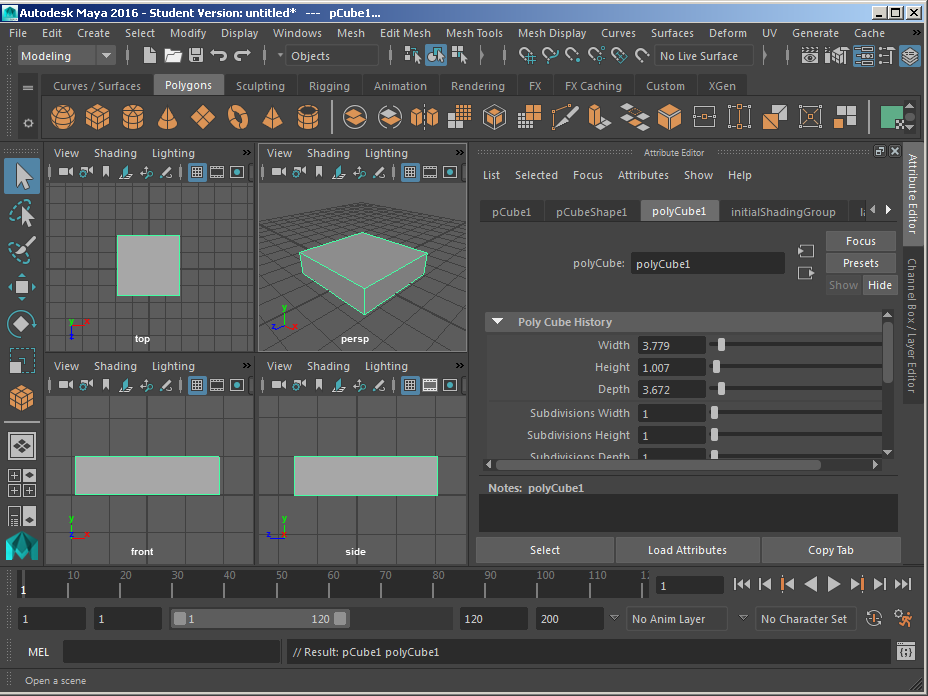
The result should resemble this:
You can zoom in on your object by hitting f (focus), which will frame the selection in the current panel. Hitting SHIFT-f will focus all views.
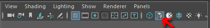
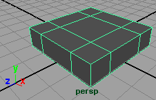
You may be seeing everything in wireframe mode (shortcut: 4). You can switch the perspective view to shaded view by hitting 5:
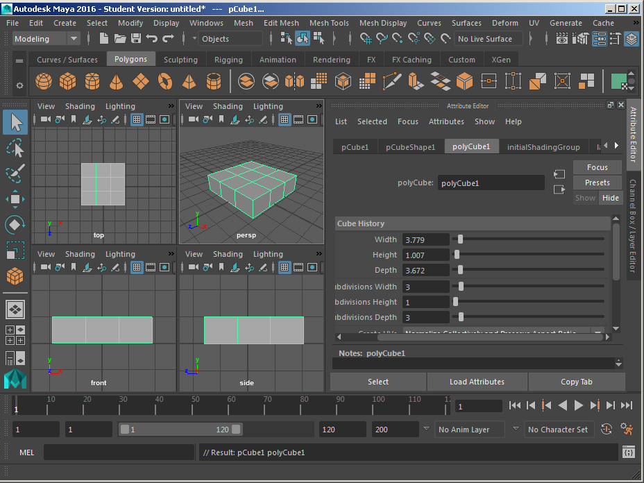
If you do not see the attribute editor on the right, you can display it by clicking on its item on the top right of the interface (the Sidebar Icons)
In the Creator tab of the Attribute Editor, most likely called polyCube1, you can enter exact values for the with, height and depth of the cube just created (the object needs to be selected)
We need more subdivision: set the Subdivision Width and Subdivision Depth to 3
Moving point to complete the base object
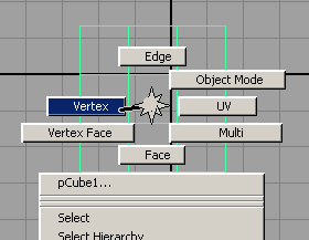
Right Click on the object to bring up the marking menu shown on the right. While holding down the RMB, select vertex and release the RMB. This will get you into vertex mode.
You should still be in selection mode. If not, you can return to it by hitting q
- In the top view, using the LMB, drag a rectangle around the second row or points (vertices) to select them.
- Switch to move (hit w)
- Of the manipulator that appears, grab the arrow pointing down (the blue z axis). It will turn yellow as you grab it with the LMB
- Drag the manipulator up, this will move the points constrained to the z-axis
Got it? Now select the other rows and move them in a similar fashion
The result should resemble this:
Now that we have our base shape, let’s add some geometry in Part 2.